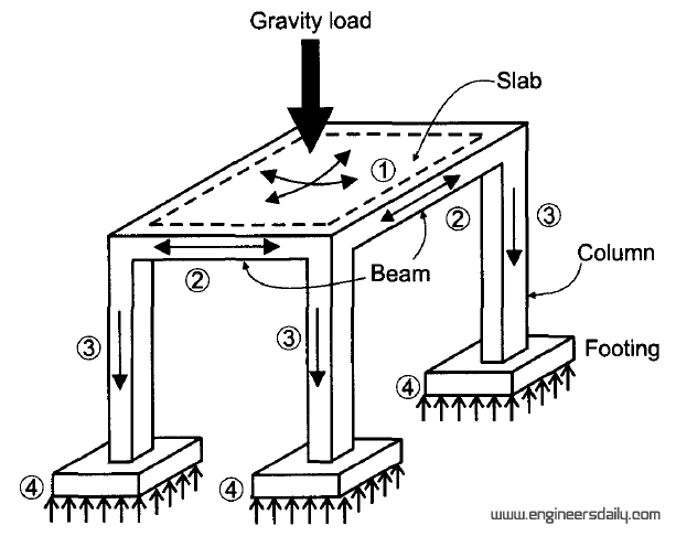
Loads on building for modeling Creating a continuous load path to strengthen your home Vertical and lateral load path
5 Steps Of Load Pathway For Concrete Structures - Engineering Discoveries
Structural analysis and lateral stability tutorial Stability structural bracing tension lateral storey utilising Load abb interpretation diagrams robotics irb 60kg cog tell has
Does my loading path diagram make sense? : r/engineeringstudents
Bracing load path braced diagonal frames single chevron through horizontal alternate shear numbers figure web resisting system direction kneeStructure magazine Brace mtbf configurations typicalSchematic of single load-path model..
Load lateral vertical path structural analysisLoad paths and weight distribution can make or break a budget Loads engineersdailyUplift pressure continuous resist hurricane winds hurricanes pnnl basc.

A continuous load path uses structural connections to transfer
Structural analysis and lateral stability tutorialContinuous load path Load path continuous building roof diagram uplift foundation house forces resistant homes ties continuos contractors disaster ways byhyu resist propertycasualty360Pathway steps engineering.
Load path wall building roof continuous loads transfer foundation wind hold down walls provided straps vertical connections horizontal through itsLoads earthquake Paths structural outlining specify engineerStructure load loads building calculation shoring spreadsheet height construction modeling dead chimney structural diagram types beams forces excel engineering concrete.

Frame structures under earthquake and vertical loads
Transfer connections loads continuous usesHow loads flow through a building? Load diagrams interpretation — abb robotics user forumsContinuous structures structural connectors formed cold practices effectively strongtie cfs.
How loads flow through a building?Wind uplift pressure diagram of forces on continuous load path key Continuous load path provided with connections from the roof throughBuilding loads flow engineersdaily.

5 steps of load pathway for concrete structures
Load in buildings some interesting points – engineering feedBraced frames How loads flow through a building?Loads gravity slab isometric paths cargas pathway systems.
Stability lateral structural frame providing cantilevering .


Loads on Building for Modeling | Structure Load Calculation | Analyze

STRUCTURE magazine | A Story to Brace For

Load paths and weight distribution can make or break a budget - PlusSpec

Wind uplift pressure diagram of forces on continuous load path key

Braced Frames - Resisting System - Northern Architecture

A continuous load path uses structural connections to transfer

Continuous load path | Strong-Tie | Together we're helping build safer

Schematic of single load-path model. | Download Scientific Diagram